Superconducting dipole magnet
 |
Project leader: p.senger(at)gsi.de |
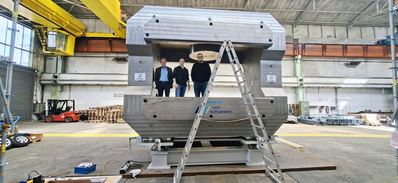
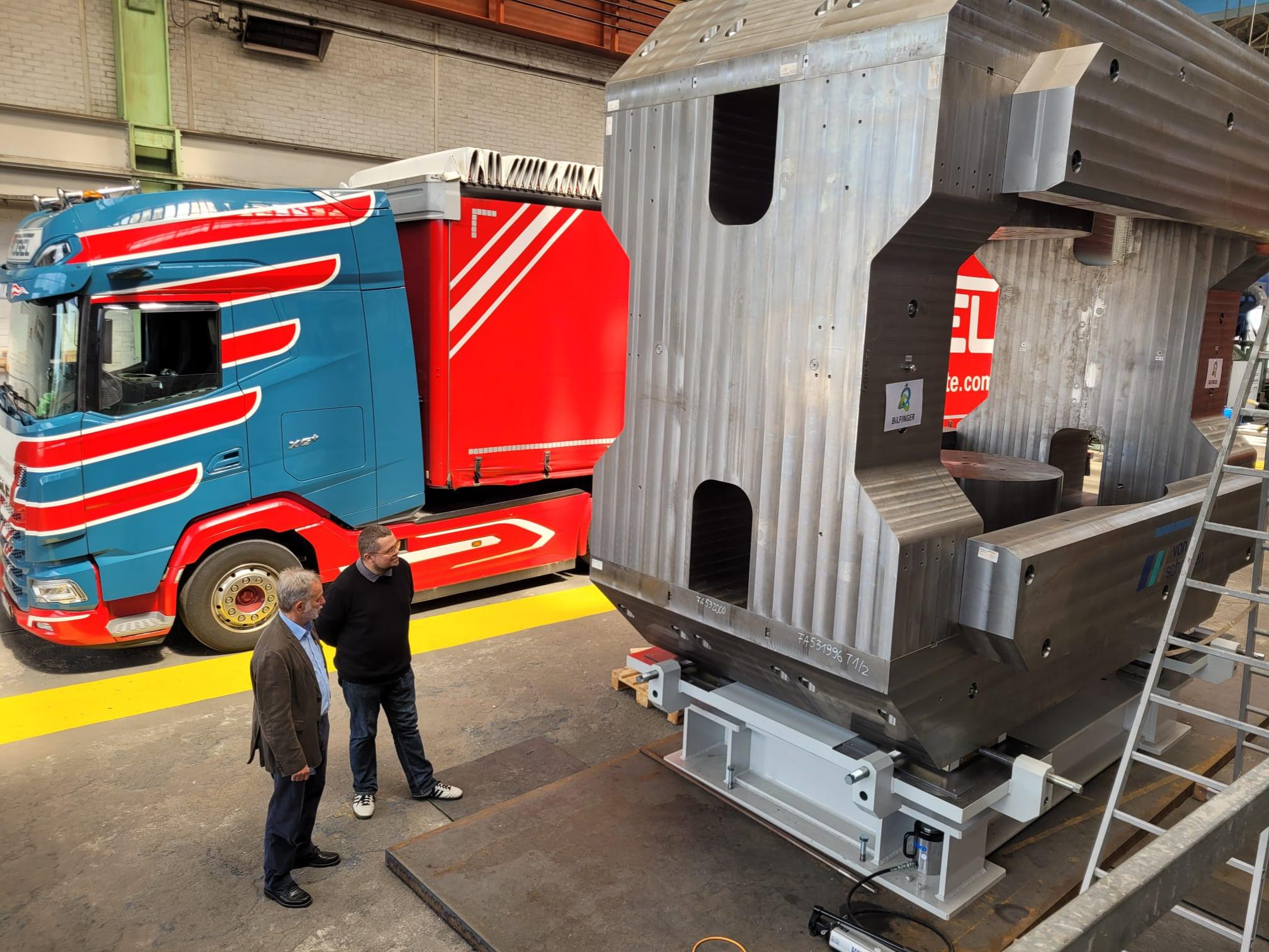
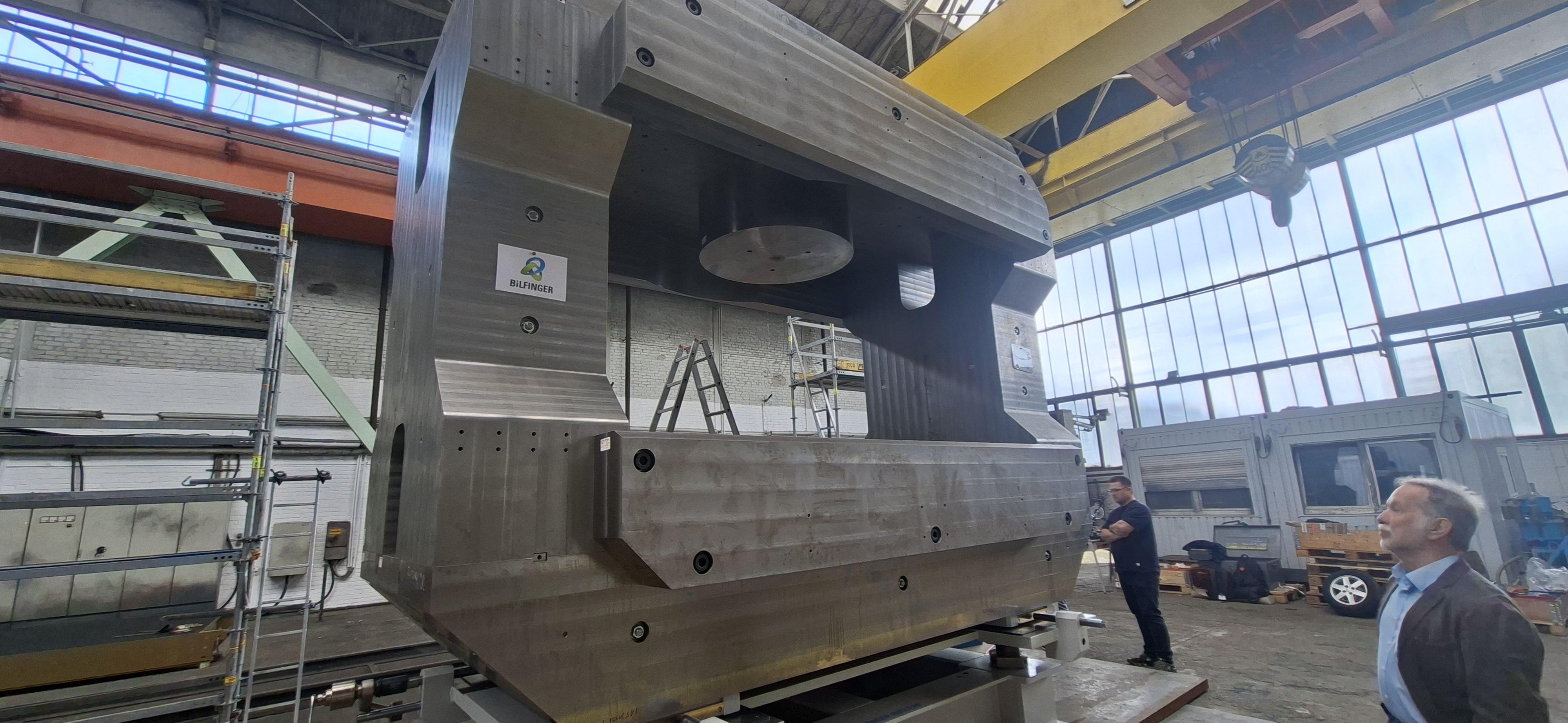
Factory Acceptance Test
 |
|
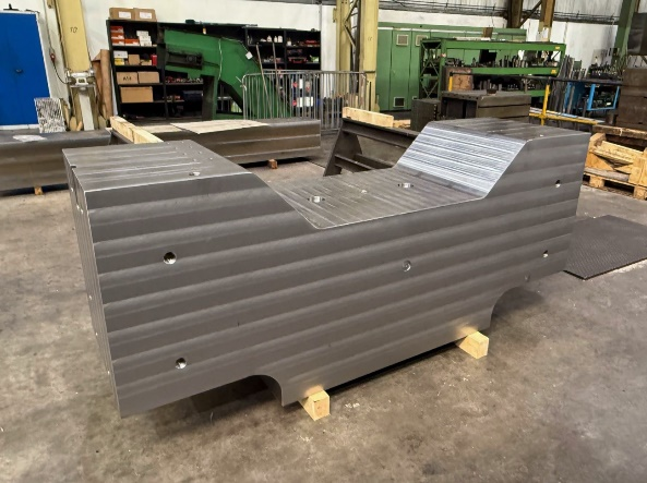
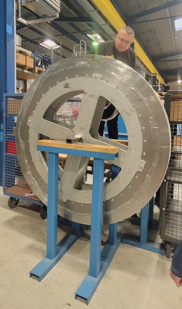
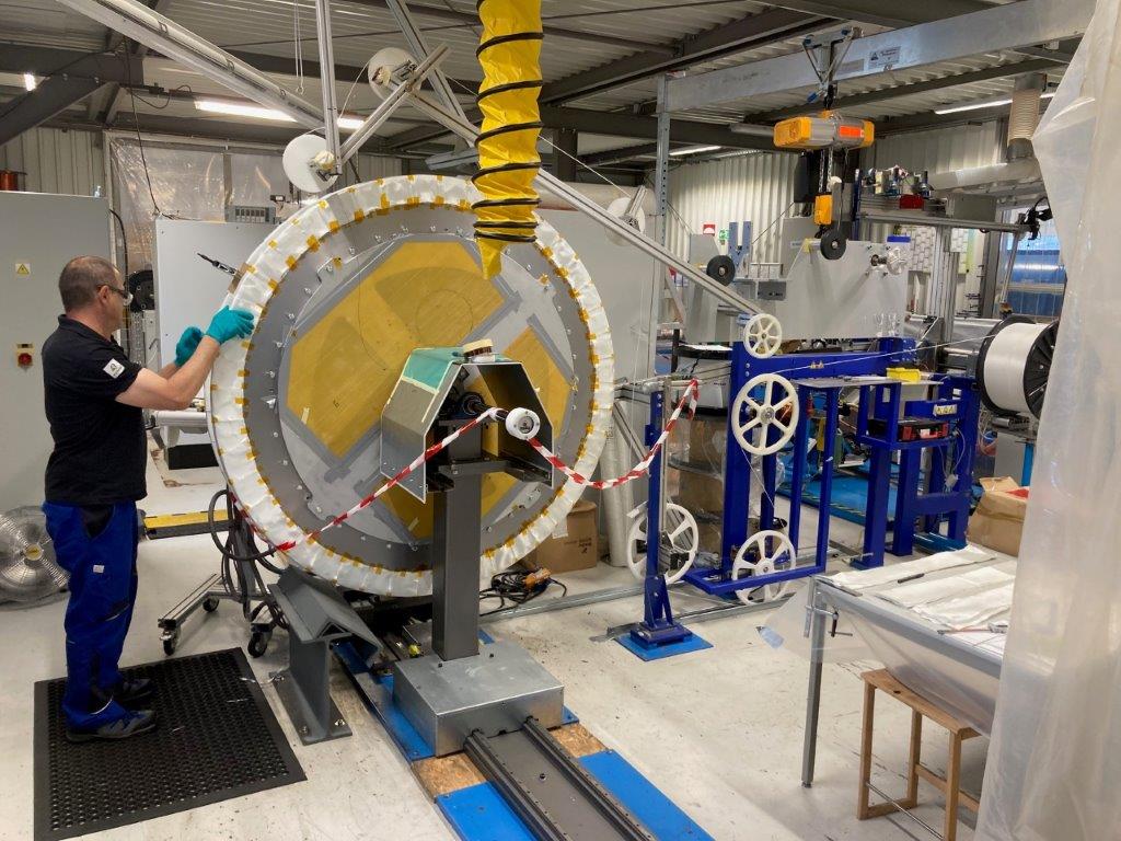
In May 2026 the Factory Acceptance Test of the magnet yoke and its support structure was successfully performed in Duisburg. The yoke was assembled with the requested accuracy of better than 0.2 mm. The horizontal alignment of the yoke was performed manually with a high-torque transmission gearbox, the vertical shift was performed by removable hydraulic jacks and thread spindles for fine adjustment of the height. The position of the yoke was measured with a laser tracker and fiducial marks at the yoke, the position accuracy was found to be better than 0.1 mm as requested. |
 |
 |
Status magnet production March 2026
 |
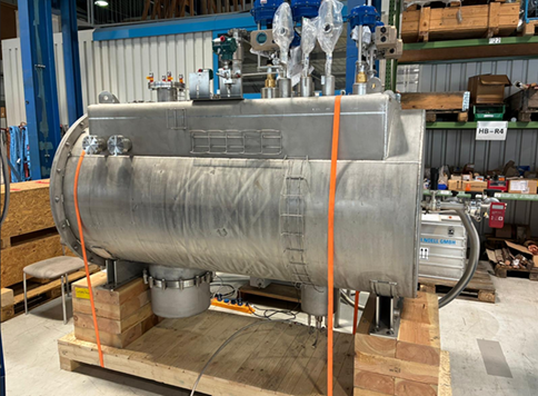
The Feeder Box is produced. It contains the liquid Helium tank and the current leads with input cables at room temperature and output bus bars to the coils at T = 4 K. The Feeder Box also hosts the stacks with cold diodes for quench protection. |
 |
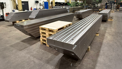 |
Most of the yoke parts are produced. |
 |
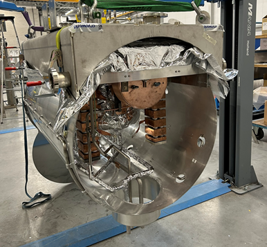
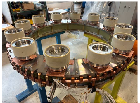 Coils with cooling and support |
The coils are equipped with the cooling structure (T= 4 K) and the support bushings. In the next step the thermal shields (T = 50 K) will be mounted. |
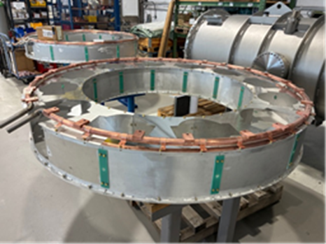 Thermal shields |
Factory Acceptance Test
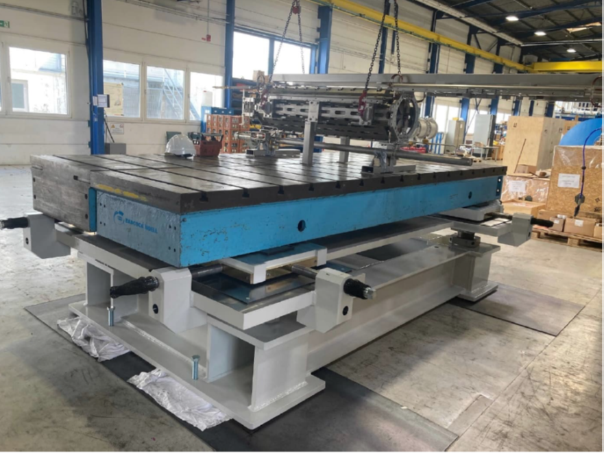 Magnet support with load |
The Factory Acceptance Test (FAT) of the magnet support has been successfully performed on 10th September 2025 at the BNET company in Würzburg. The support carried a load of 10 tons together with a SIS100 quadrupole magnet with fiducial marks for alignment with two laser trackers. The load was shifted horizontally and vertically, rotated and tilted within the required limits with a precision of 20 micrometer. The test will be repeated with the magnet yoke as load (weight 150 tons) in 2026. |
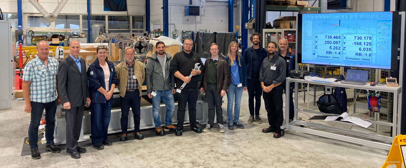 Teams of GSI and BNET participating in the test |
|
The first coil of the CBM magnet is ready for impregnation. The coil consists of 4 superconducting cables, each with a length of about 5 km, which will be connected via joints outside the coil. |
 |
Coil Support Pressure Test
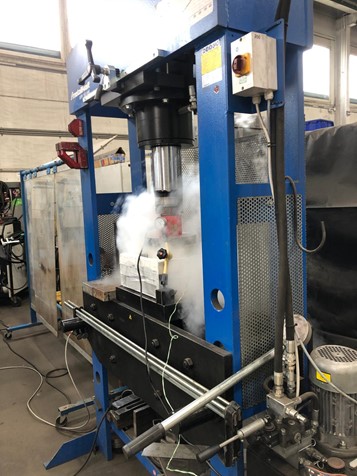 Pressure test of the bushing at liquid Nitrogen temperature |
Pressure test of a coil support bushing for the CBM superconducting dipole On 6th of June 2025 the CBM Magnet team visited the company BNET in Würzburg which is constructing the superconducting dipole for the CBM experiment. The team attended a pressure test of a coil support bushing, one of the most critical components of the magnet. Each coil of the magnet is supported by 12 bushings, which have to compensate for a Lorentz force corresponding to 309 t, while thermally isolating the cold coil (T = 5 K) from the yoke (at room temperature). Each bushing consists of three rings made of composite material G11 and two stainless steel rings, with different diameters and heights and alternatively nested. The total diameter of the bushing is 226,85 mm, the total height is 180 mm. In the first test the bushing was exposed to a force of 313 kN over 10 minutes, which is about 10% above the maximum load expected for one bushing. The bushing was elastically deformed by 2.42 mm, which is 1.2% of the height. For the second test, the lower part of the bushing was cooled by liquid Nitrogen to simulate the real situation during operation of the magnet. After cooling down, the bushing shrank by 1.15 mm, and after applying again 313 kN over 10 minutes, the bushing was elastically deformed by 1.63 mm. While the lower part of the bushing was cooled down to -190°C, the upper part was still at +20°C. Therefore, both the tests of pressure and of the heat loss were successful. According to the mechanical calculation based on the material properties of the bushing, the upper limit for the force is 600 kN. |
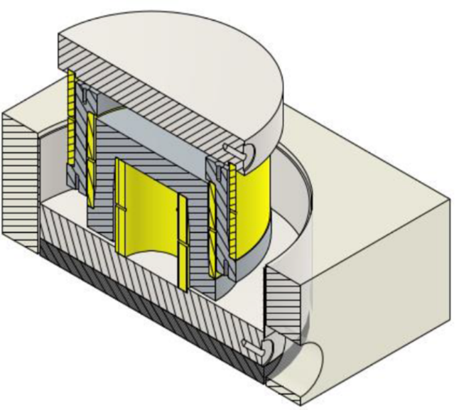 Coil support bushing with three G11 rings (yellow) and two stainless steel rings (grey) |
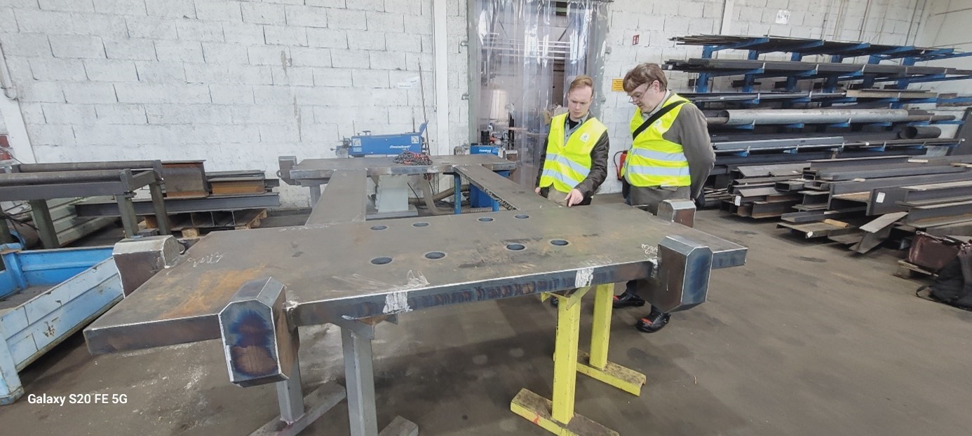 The magnet support plate, a component of the alignment system |
 Winding of the coil for the CBM magnet |
Moreover, the coil winding machine has been set up in the clean room, and the preparations for winding have started. Also, parts of the magnet support have been produced. |
Magnet description
|
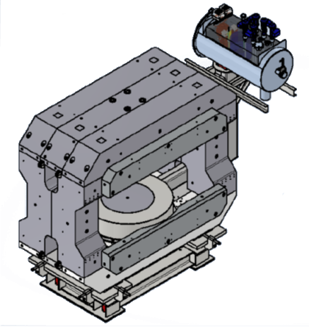
The magnet with the feeder box on its adjustable support structure. |
The CBM superconducting dipole magnet provides a vertical magnetic field with a magnetic field integral of 1 Tm which is needed to obtain a momentum resolution of Δp/p=1 % for track reconstruction at FAIR beam energies. The magnet gap has a height of 147 cm and a width of 330 cm in order to accommodate the STS detector system with a polar angle acceptance of ±25° and a horizontal acceptance of ±30°. The total weight of the magnet is about 160 t. The yoke is equipped with field clamps in order to reduce the stray field to an acceptable level in the area of the RICH-detector. |
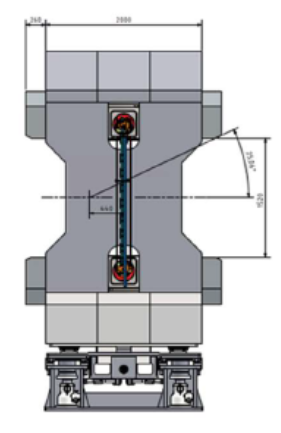
Vertical cut through the magnet. |
|
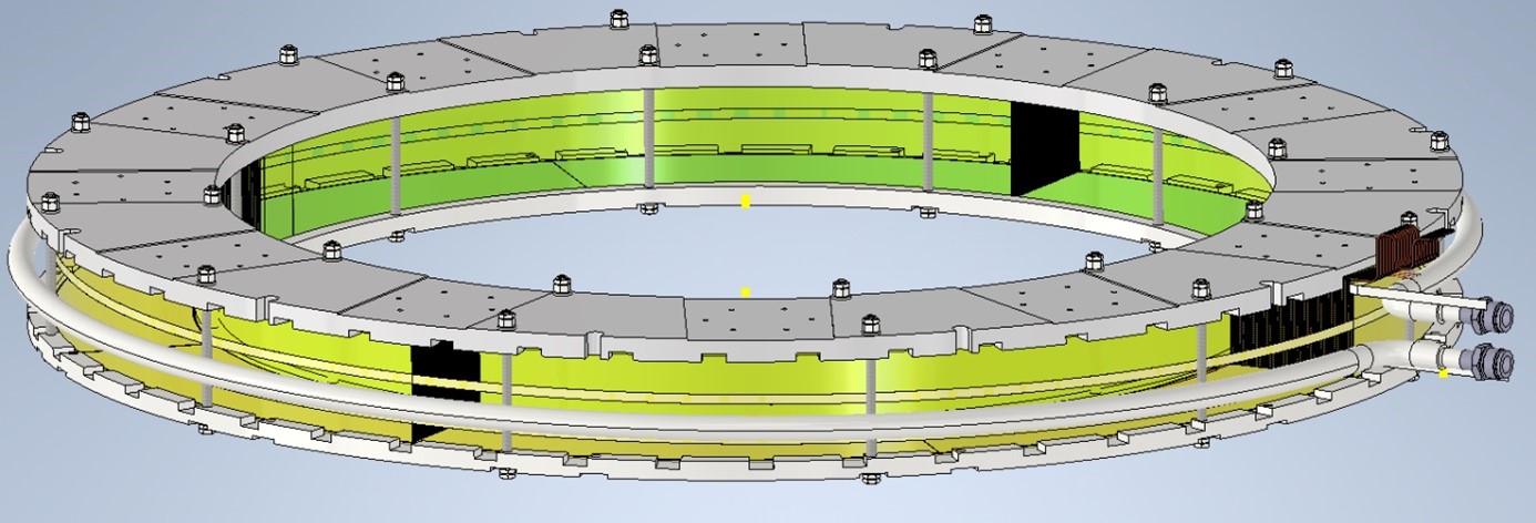
Coil structure and cooling The magnet consists of a pair of superconducting circular coils and a warm iron yoke with framed shape. Each coil is suspended in a stainless steel vacuum vessel. The coil conductor is of the “wire-in-channel” type, i.e. a NbTi strand is embedded in a rectangular copper conductor. The copper to superconductor ratio is 5:1. Each coil requires a conductor with a length of almost 20 km. As only conductors with a maxi-mum length of 6 km can be delivered, each coil winding pack consists of 4 supercon-ducting sections connected with soldered joints. The total number of turns is 4100, the operating current at maximum field is 311 A, the stored energy of the magnet is 5.36 MJ.
Each coil will be indirectly cooled with LHe in a helical tube surrounding the coil. The LHe tube is connected via copper strips to copper plates above and below the coil winding pack. The copper plates are pressed towards the coil winding pack by stain-less steel plates to assure good thermal contact. |
|
Coil support system The mechanical support of the coils has to fix the coils and to compensate the Lorentz force equivalent to 300 t, and, at the same time, to prevent heat exchange between the cold mass of the coil (LHe temperature) and the coil cryostat (room temperature). This support is realized by 6 tension rods and 12 bushings. The tension rods fix the coils, while the bushings compensate the pressure of the Lorentz force. The bushings consist of two stainless steel tubes and three G11 (fiberglass laminate) tubes, which are arranged concentrically and inserted into each other. The inner bushing is fixed, whereas the outer bushing is sliding and arranged on bronze sliding plates. This plate is directly connected to the cryostat and the sliding support plate is connected with the outer G11 bushing. The bronze sliding plates allow shrinkage of the coils during cool down and under nominal current. They guide the sliding in radial direction because during cool down the coil will shrink in radial direction. Therefore, the G11 bulk with the support plate can slide on the bronze sliding system in radial direction. |
|
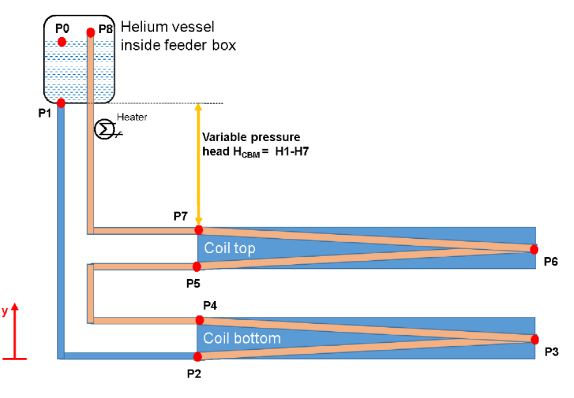
Cryogenic system A liquid helium thermosiphon system is used for the cooling of the coils. It consists of a vessel with liquid Helium at a temperature of 4.6 K located inside the feeder box above the two coils. The working principle of a thermosiphon is based on the natural circulation of helium in the system. The flow is created by the density difference be-tween the heated fluid with a gaseous component in the return line and the cold fluid in the supply line. The circulation can be additionally driven by a heater in the return line. |
 |
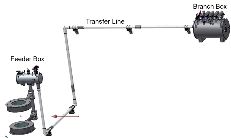 The cryogenic distribution is provided by the branch box, which is connected to the feeder box by a transfer line. |
|
Quench protection and detection A passive quench protection system in the form of cold rectifier diodes is foreseen for the CBM magnet coils. Each coil is sub-divided into 4 sections, and each section is protected by 4 pairs of back-to back diodes. This redundant combination of diodes takes into account two failure scenarios of diodes for both current directions: The damaged diode is short-circuited and allows current to flow through, and the other case, the diode no longer allows current to flow. In the case of a quench the power supply’s output is deactivated via its interlock function and the stored energy is dissi-pated within the coils and the diode racks. The quench detection is based on a bal-anced voltage principle with two coils being balanced against one another. Voltage taps located at the inlet and outlet of the coils at the joint between the two coils serve as quench sensing. The quench protection is realized with a system of cold diodes. The diodes are connected to copper blocks inside the so-called feeder box, and are cooled to LHe temperature. The feeder box contains the LHe bath, the current leads, the bus bars, and the cold diodes on copper blocks. |
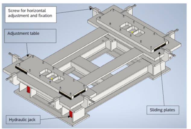 |
Support structure and alignment system The magnet support consists of four solid feet made of 30 mm steel sheets. Trape-zoidal threaded spindles are centered in the foot construction, which allows the mag-net to move in the vertical direction. At the upper end of the spindles there are ball sockets carrying an adjustment table, which allows the shift of the magnet in horizon-tal direction on sliding bronze plates. The alignment parameters are as follows:
|
 |
The design and construction of the magnet is performed by Bilfinger Nuclear and Energy Transition (BNET, Würzburg) in collaboration with GSI. |