Silicon Tracking System (STS)
 |
Project leader: c.j.schmidt(at)gsi.de |
 |
Technical coordinator: j.heuser(at)gsi.de |
|
Detector overview
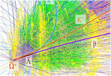
CBM simulation (UrQMD, Geant, CbmRoot): |
The Silicon Tracking System (STS) is CBM’s core detector to identify the charged particles that are created when the nuclear beams extracted from the SIS100 accelerator interact with the target. Hundreds of particles originate from the collision of a single beam ion with the target material. The interactions take place at rates up to ten million times per second. Eight STS tracking stations sample multiple intersection points along the particles’ flight paths. This allows reconstructing the particle trajectories (“tracks”) and to determine from their curvatures in the dipole magnetic field the particle momenta – a central quantity for CBM physics analyses. Unstable particles are identified through their decays into daughter particles, with their tracks pointing to vertices separate from the primary collision point. |
|
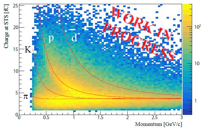
The particle detection technology is based on highly-segmented double-sided Silicon microstrip sensors read out with fast self-triggering front-end electronics. Five-dimensional particle hit information (sensor channel coordinates, time and charge) is streamed at rates up to 1 Tbit/s to a compute farm where the trajectory reconstruction and finally the collision event analysis are performed. The STS hits are determined with 15 micrometer spatial resolution, the associated time is measured with 5 ns resolution. The STS detector can further contribute to particle identification through the measurement of energy loss. |
Energy loss vs. Momentum |
|
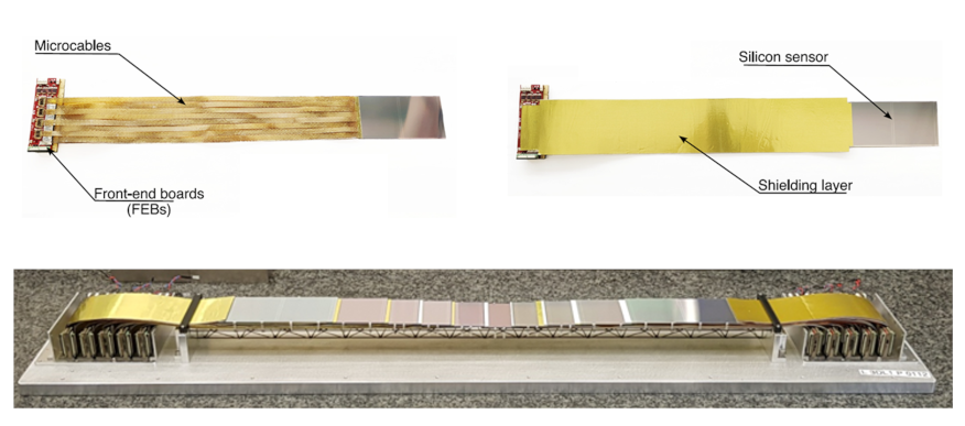
STS ladder (bottom) comprising 10 detector modules (top). |
A key design goal was to minimize particle multiple scattering in the physics aperture, while fulfilling the high detection-rate requirement. Several measures were taken:
|
|
Design of a STS half-unit. |
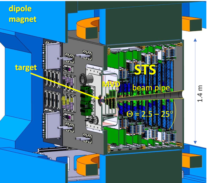
The STS system integration realizes eight tracking stations from 20 mechanical half-units, which are assemblies of ladders, read-out and powering electronics as well as cooling infrastructure on C-shaped aluminum frames. In the detector, they are located evenly spaced left and right from the beam axis between 0.3 m and 1 m distance downstream of the target. Their low-mass construction allows for momentum measurement with resolution better than 2%. |
|
The tracking stations are installed into an enclosure with thermally insulating walls. Thermal runaway of sensor currents in the high-radiation environment will be avoided through the application of sensor air cooling down to 0° C. The readout and powering electronics, dissipating up to 40 kW, will be cooled in contact with a cold liquid circulated in cooling plates. All power, cooling and communication links are internally routed to the upstream enclosure wall where supplies in the CBM hall can be branched to. At the upstream wall, the STS box also comprises the vacuum chamber with the interaction-target and the Micro Vertex Detector (MVD). A 0.5 mm thick secondary particle track window separates target chamber and STS fiducial volume. It is integrated with the 1 mm thick STS beam pipe section forming one structure made from carbon fiber composite. |
CAD model of the STS detector system in the dipole magnet |
|
Prototype tests in beam
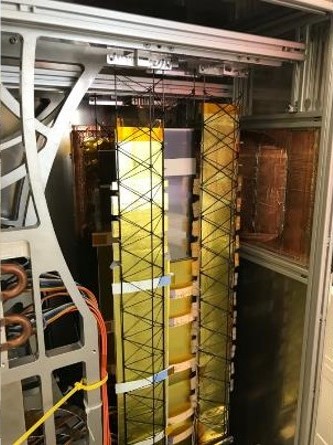
STS in the mCBM demonstrator experiment at GSI-SIS18 |
Test experiments under realistic conditions in beam, most recently in the mCBM demonstrator experiment at GSI-SIS18 and in the E16 experiment at J-PARC, have proven that design concept and prototype elements match STS specifications. Substantial experience has been gained on components and system integration, operation, data acquisition and data analysis towards the full-scale STS detector. |
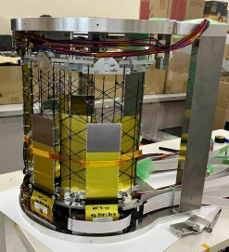
STS pre-series modules in the J-PARC E16 experiment, commissioning run 0e, 2024 |
|
Construction of the STS system:
|